
 NEWS List
How to Size the Right Fiberglass Conduit Rod for Different Duct Diameters
1. Why Wrong Sizing Causes Rod Breakage, Jams and Project Delays
The most common mistake when choosing a fiberglass conduit rod is to look at the duct diameter alone.
A 50 mm duct does not automatically require one specific rod diameter.
Why?
Because the actual installation load depends on the entire route.
A short 50 mm conduit with two gentle bends may be much easier to rod than a 50 mm underground duct running 150 meters through several manholes.
OSHA notes that smaller conduit diameters can increase contact points and resistance between the conduit and wire, while bends in conduit create restriction points that increase the force required for pulling.
The same principle applies to the rod itself.
Rod Too Small
An undersized rod may have:
Excessive flexing
Poor pushing stiffness
Difficulty crossing long horizontal sections
Greater sensitivity to bends
Higher risk of permanent deformation or damage
Difficulty pushing a pulling line through a complicated route
For example, using a very thin 4 mm rod in a long underground duct may be possible from a dimensional perspective, but the rod may lack the stiffness needed for efficient long-distance feeding.
Rod Too Large
Oversizing creates a different problem.
A thick rod may:
Be difficult to push through tight bends
Require a larger minimum bend radius
Increase contact with the duct wall
Require more storage space
Increase transportation weight
Be unnecessarily expensive
A manufacturer's specifications illustrate why this matters: General Machine Products lists minimum bend diameters of approximately 135 mm for a 4.5 mm rod, 250 mm for a 6.7 mm rod, 310 mm for a 9 mm rod, and 450 mm for a 12 mm rod.
Therefore:
Bigger does not automatically mean better.
The correct rod is the smallest practical diameter that provides sufficient pushing stiffness and load capacity for the actual route.
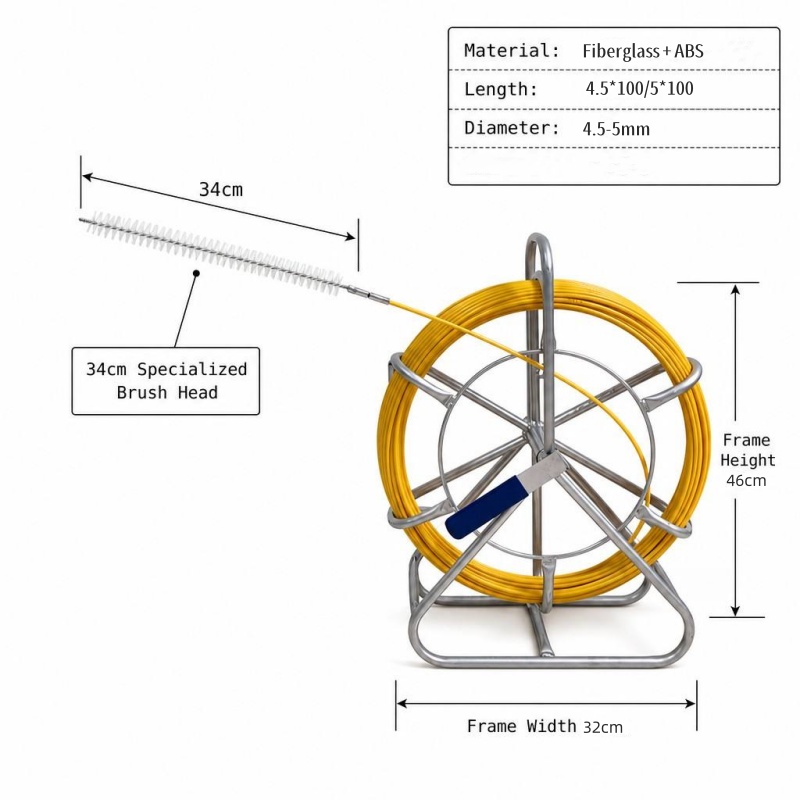
2. Duct Diameter Reference Table: Match 4 mm–16 mm Rod to Small, Medium and Large Conduits
The following table provides a practical starting point for selecting fiberglass conduit rods.
These ranges should be treated as field-selection guidance, not mandatory standards.
Fiberglass Rod Diameter Suggested Duct Diameter Typical Application Typical Route
4 mm 10–30 mm Small conduit, indoor wiring, FTTH Short/light-duty
5 mm 20–40 mm Small telecom/electrical conduit Short to medium
6 mm 25–60 mm Building cable routes, small ducts Short to medium
7 mm 30–80 mm Telecom and utility ducts Medium
8 mm 40–90 mm Medium conduit and cable ducts Medium
9 mm 50–120 mm Underground telecom ducts Medium to long
10 mm 60–140 mm Large communication ducts Medium to long
11 mm 70–150 mm Underground duct systems Long
12 mm 75–160 mm Large telecom/utility ducts Long/heavier duty
13 mm 75–170 mm Large ducts and demanding routes Long/heavy duty
14 mm 80–190 mm Large underground ducting Long/heavy duty
15 mm 90–200 mm Large utility/telecom ducts Long/heavy duty
16 mm 100 mm+ Large ducts and high-load applications Heavy duty
One commercial fiberglass duct-rodder specification provides a similar reference, listing 4 mm rods for 10–30 mm conduits, 6 mm rods for 25–76 mm conduits, 10 mm rods for 75–140 mm conduits, 14 mm rods for 76–190 mm conduits, and 16 mm rods for conduits above 100 mm.
However, another professional manufacturer uses different performance ratings and size groupings. Condux, for example, lists 5 mm, 6 mm, 8 mm, 11 mm, and 13 mm duct rodders with different pull strengths and minimum bending radii.
This demonstrates an important purchasing rule:
Do not compare rod diameter without comparing the specification sheet.
Two rods with the same nominal diameter may have different:
Fiberglass core construction
Resin composition
Outer jacket
Tensile strength
Pull strength
Minimum bending radius
End-fitting design
Fatigue resistance
Small Ducts: 4–6 mm
For ducts approximately 10–60 mm in diameter, smaller fiberglass rods are usually more practical.
Typical applications include:
Residential conduits
Indoor communication wiring
FTTH customer drops
Small electrical conduits
Building automation cables
Data and low-voltage systems
A 4 mm rod is particularly useful where the conduit is narrow and the route is relatively short.
For a more demanding route, moving to 5 or 6 mm can provide additional pushing stiffness.
Medium Ducts: 7–10 mm
Medium-sized rods are suitable for:
Telecom ducts
Building-to-building communication pathways
Underground communication conduits
Industrial cable routes
Utility ducts
The 8–10 mm range offers a useful balance between flexibility and stiffness.
For example, Condux lists an 8 mm rod with a rated pull strength of approximately 4.2 kN, while its 11 mm and 13 mm rods are also rated at approximately 4.2 kN and 6.2 kN respectively.
This is another reason why diameter alone should not determine your selection.
Large Ducts: 11–16 mm
Large fiberglass rods are more appropriate for:
Long underground ducts
Utility corridors
Large telecom conduits
Industrial facilities
Large cable pathways
Heavy pulling-line installation
The additional stiffness makes it easier to push the rod over long horizontal distances.
However, these rods also require larger bend radii.
Therefore, a 16 mm rod may be ideal for a large, relatively straight underground duct but unsuitable for a small conduit containing several tight turns.
3. Route Factor Adjustment: Extra Tension Reserve for Bends, Manhole Turns and Long Runs
Duct diameter is only the first selection factor.
The second is route difficulty.
A useful way to think about rod selection is:
Required rod capacity = basic route load × route difficulty factor + safety reserve
This is not a universal calculation formula. It is a practical engineering concept for deciding when to move up one rod size.
Factor 1: Number of Bends
Every bend changes the direction of the rod and increases contact with the duct.
OSHA notes that bends in conduit create restriction points and increase the force needed for pulling.
For example:
Straight 40 m duct → 6 mm rod may be sufficient
40 m duct + four 90° bends → consider 7–8 mm
The larger rod provides greater pushing stiffness, but its minimum bend radius must still be compatible with the actual route.
Factor 2: Manhole Turns
Manhole transitions can be more demanding than ordinary conduit bends.
The rod may need to:
1.Exit the first duct
2.Change direction
3.Enter another duct
4.Continue horizontally
The transition should therefore be evaluated as part of the complete route.
Do not simply measure the straight-line distance.
Measure the actual path.
Factor 3: Long Runs
Long-distance routes require additional attention to:
Rod stiffness
Friction
Duct cleanliness
Internal obstructions
Number of bends
Elevation changes
Rod fatigue
For example:
Route Suggested Approach
20 m straight Standard rod
50 m straight Standard/medium rod
100 m straight Medium/heavy rod
150+ m Heavy-duty rod or sectional/mechanical system
150+ m with many bends Heavy-duty rod + route inspection + lubrication
Longer routes do not necessarily require a larger rod in every case.
If the route is very tight, increasing rod diameter may actually make feeding harder.
The better approach is to evaluate stiffness versus flexibility.
Factor 4: Elevation Changes
A rod traveling uphill or through vertical transitions may require additional pushing force.
Corning's fiber-optic installation procedure recommends attention to severe offsets and uphill elevation changes, and notes that lubricant may be needed before bends and difficult transitions.
Therefore, when a route includes:
Vertical rises
Downward drops
Multiple elevation changes
Sharp transitions
consider moving up one rod size only after checking the minimum bend radius.
4. Cable Compatibility: How to Match Rod Breaking Tension to Your Cable Weight
This is one of the most important points in rod selection.
A common mistake is:
“The cable weighs 100 kg, so I need a rod with a breaking load greater than 100 kg.”
This is not the correct way to calculate cable-pulling requirements.
Cable pulling force is affected by:
Cable weight
Cable length
Friction
Conduit material
Lubrication
Number of bends
Bend radius
Cable diameter
Cable construction
Elevation
Pulling speed
For fiber-optic cable, the manufacturer's specified maximum installation tensile force is particularly important.
Corning explicitly states that fiber-optic cable can be damaged if its specified maximum tensile force is exceeded and recommends checking the cable specification sheet. For longer pulls, tension monitoring is recommended.
Therefore, the rod should have enough capacity to perform the job without becoming the weak link, but the cable's maximum allowable tension must never be exceeded.
Rod Breaking Strength Is Not the Same as Recommended Working Load
This distinction is critical.
Suppose a fiberglass rod has:
Rated tensile strength: 6.2 kN
That does not automatically mean:
Recommended continuous working load = 6.2 kN
Different manufacturers may define:
Breaking load
Rated tensile strength
Pull strength
Working load
Safety factor
differently.
For example, GMP lists a 4.5 mm rod with a rated tensile strength of 6.2 kN but a rated pull strength of only 1.6 kN.
That is a major difference.
Therefore, when comparing suppliers, always ask:
“Which load rating should be used for normal operation?”
Do not select a rod based solely on the largest number printed on the product page.
Cable Weight Is Only One Part of the Calculation
For example:
A 100 m cable weighs 80 kg.
That does not mean the rod experiences only an 80 kg load.
If the route contains several bends and significant friction, the required pulling force can be much higher.
Conversely, a lightweight fiber cable on a smooth, straight pathway may require relatively little pulling force.
For demanding cable installations, the correct approach is to estimate or measure pulling tension using the cable manufacturer's installation specifications and appropriate engineering tools.
Corning recommends calculating pulling tension, conduit fill, and sidewall pressure for planned fiber-optic conduit pulls.
5. Multi-Size Scenarios: Universal Selection Tips for Mixed Cable Sizes
Contractors rarely work on only one duct size.
A telecom company may encounter:
25 mm indoor conduit
50 mm building conduit
75 mm underground duct
100 mm utility duct
150 mm multi-cable duct
Buying a different rod for every application can increase inventory cost.
A better strategy is to build a three-level rod portfolio.
Level 1: Small Rod
4–6 mm
For:
Indoor FTTH
Residential wiring
Small conduits
Short cable routes
Level 2: General-Purpose Rod
7–10 mm
For:
Telecom construction
Building projects
Medium ducts
General underground work
This should normally be the contractor's most versatile category.
Level 3: Heavy-Duty Rod
11–16 mm
For:
Large ducts
Long underground runs
Utility projects
Heavy pulling-line installation
This three-size strategy is often more practical than purchasing a separate rod for every conduit diameter.
Universal Selection Rule
When two rod sizes both appear suitable, choose according to the following priority:
1. Can it physically pass the route?
↓
2. Is its minimum bend radius compatible?
↓
3. Does it have sufficient pushing stiffness?
↓
4. Does its rated working/pull capacity meet the application?
↓
5. Is there sufficient reserve for the route conditions?
This is more reliable than simply choosing the largest diameter.
6. Quick Reference Flowchart for On-Site Engineering Teams
Use the following decision process before opening the duct rodder reel.
Step 1 — Measure the Duct
What is the actual internal diameter?
10–30 mm → Start with 4 mm
20–40 mm → Start with 5 mm
25–60 mm → Start with 6 mm
30–80 mm → Start with 7 mm
40–90 mm → Start with 8 mm
50–120 mm → Start with 9 mm
60–140 mm → Start with 10 mm
70–150 mm → Start with 11 mm
75–160 mm → Start with 12 mm
75–170 mm → Start with 13 mm
80–190 mm → Start with 14 mm
90–200 mm → Start with 15 mm
100 mm+ → Consider 16 mm
These ranges are based on a commercial duct-rodder reference table and should be cross-checked against your selected manufacturer's specifications.
Step 2 — Check the Route
Is the route straight?
→ Yes: continue with the initial size.
Does it contain multiple bends?
→ Yes: check the rod's minimum bend radius before increasing diameter.
Step 3 — Check the Length
Is the route long?
→ Yes: consider additional pushing stiffness and rod capacity.
Step 4 — Check the Cable
Is the cable lightweight fiber?
→ Prioritize cable tension limits and bend radius.
Is it a heavier power or utility cable?
→ Consider a larger rod and potentially mechanical pulling equipment.
Step 5 — Check the Load Rating
Is the required load within the manufacturer's rated pull/working capacity?
→ Yes: proceed.
→ No: select a higher-capacity rod or mechanical pulling method.
Step 6 — Final Safety Check
Before installation:
Inspect the rod
Check end fittings
Check guide head
Check duct condition
Remove obstructions
Confirm bend radius
Confirm cable pulling tension
Prepare lubricant where appropriate
Confirm communication between workers
For fiber-optic cable, Corning recommends appropriate pulling grips, swivels, lubrication, and tension monitoring for longer pulls.
7. Common Sizing Mistakes and How to Fix Them Before Installation
Mistake 1: Choosing Only by Duct Diameter
A 100 mm duct does not automatically require a 16 mm rod.
Fix:
Consider:
Route length
Bend count
Bend radius
Cable type
Required pushing stiffness
Rod pull rating
Mistake 2: Always Choosing the Largest Rod
Bigger rods are stiffer, but they also require larger bending radii.
A large rod can become difficult to feed through tight bends.
Fix:
Choose the smallest rod that provides adequate stiffness and load capacity.
Mistake 3: Confusing Breaking Load with Working Load
A rod advertised as having a high breaking strength may not be intended for continuous operation at that load.
Fix:
Ask the manufacturer for:
Rated pull strength
Working load
Breaking strength
Safety factor
End-fitting strength
Mistake 4: Ignoring the Rod's Minimum Bend Radius
This is particularly important when moving from 4–6 mm rods to 10–16 mm rods.
As rod diameter increases, minimum bending dimensions can increase significantly.
For example, GMP lists minimum bend diameters of approximately 135 mm for its 4.5 mm rod, 310 mm for its 9 mm rod, and 450 mm for its 12 mm rod.
Fix:
Measure the actual bend radius of the route before selecting the rod.
Mistake 5: Ignoring Duct Condition
A nominally large duct can still be difficult to rod if it contains:
Mud
Water
Debris
Broken innerduct
Existing cables
Damaged conduit
Sharp edges
Fix:
Perform a route inspection before selecting the final rod.
If necessary, use a smaller pilot rod first.
Mistake 6: Selecting the Rod Based on Cable Weight Alone
Cable weight does not directly equal pulling tension.
Fix:
Check the cable manufacturer's:
Maximum installation tension
Minimum bend radius
Recommended pulling method
Lubrication requirements
For fiber-optic cable, exceeding the specified maximum tensile force can damage the cable and potentially affect its warranty.
Mistake 7: Using a Rod When a Mechanical Puller Is Required
A fiberglass rod is excellent for creating a pulling path and installing a pulling line.
It is not automatically a substitute for a powered cable-pulling system.
OSHA recommends mechanical wire pullers as a way to reduce manual pulling force for demanding cable installations.
Fix:
For long, heavy, or high-tension cable installations:
Fiberglass rod → pulling line → calibrated mechanical puller → cable
This approach provides better control than trying to use the rod itself as a heavy-duty cable pulling winch.
Final Selection Checklist
Before choosing a fiberglass conduit rod, confirm these seven parameters:
Parameter What to Check
1. Duct diameter Actual internal diameter
2. Rod diameter 4–16 mm or manufacturer equivalent
3. Route length Short, medium, or long
4. Bend conditions Number and radius of bends
5. Cable type Fiber, telecom, electrical, utility
6. Load requirement Rated pull/working capacity
7. Minimum bend radius Must suit the actual route
The final selection can be summarized as:
Small duct + short route → smaller flexible rod
Medium duct + general telecom work → medium fiberglass rod
Large duct + long straight route → larger heavy-duty rod
Many tight bends → prioritize flexibility and minimum bend radius
Heavy cable/high tension → use an appropriately rated rod and mechanical pulling equipment
Conclusion: The Right Rod Is the One That Matches the Entire Route
Sizing a fiberglass conduit rod is not simply about matching one number to another.
The duct diameter tells you where to start.
The route tells you how much flexibility and pushing stiffness you need.
The cable tells you how much pulling force is acceptable.
And the manufacturer's specification tells you whether the selected rod is actually capable of performing the job safely.
For most contractors, a practical inventory covering 4–6 mm, 7–10 mm, and 11–16 mm provides a useful starting range for small, medium, and heavy-duty duct work.
But the best selection should always be verified against the actual manufacturer's specifications.
The key principle is simple:
Choose the smallest practical rod that can reliably navigate the duct while providing enough stiffness and rated capacity for the route—and never allow the pulling process to exceed the cable's own installation limits.
With the correct rod diameter, proper route assessment, and appropriate pulling technique, installers can reduce jamming, avoid unnecessary rod damage, improve feeding efficiency, and make cable installation much more predictable.