
 NEWS List
A Complete Buying Guide for Cable Installation Teams
1. What Is a Fiberglass Duct Rodder and How Does It Work for Cable Snaking?
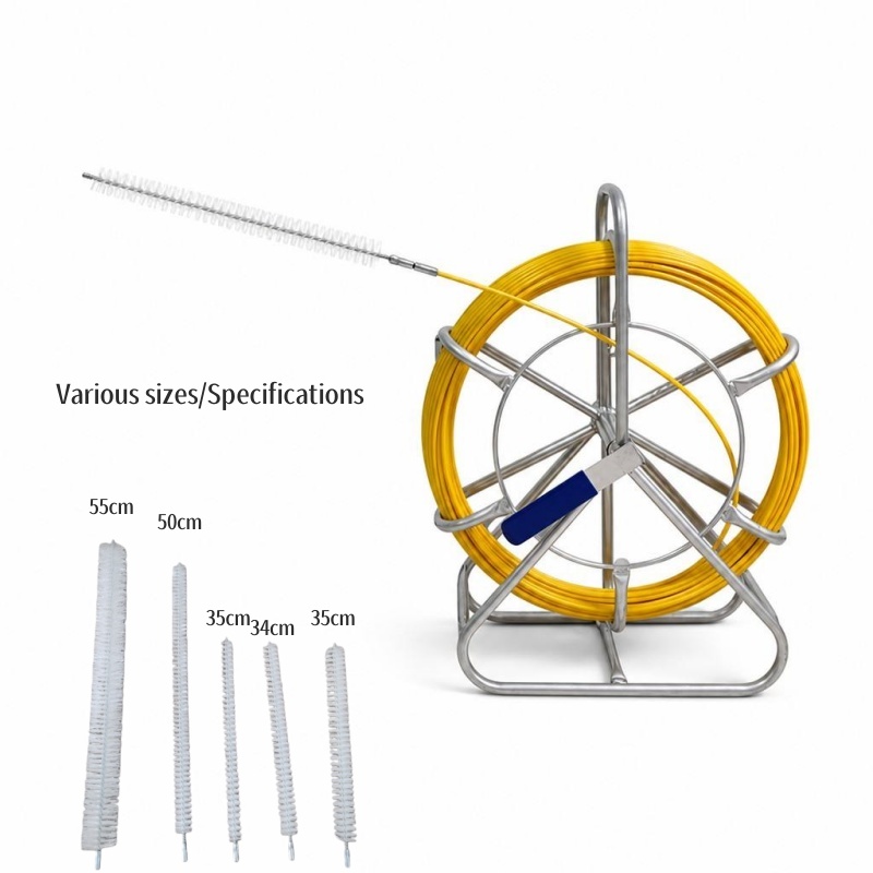
A fiberglass duct rodder is a cable-installation tool consisting primarily of a flexible fiberglass rod wound onto a reel or frame.
The rod is pushed through an existing conduit, duct, pipe, or underground pathway. Once it reaches the opposite end, a cable, pulling rope, or pulling line is attached to the rod's pulling head. The operator then pulls the rod back, bringing the cable or pulling line through the duct.
In simple terms, the working principle is:
Rod insertion → Rod reaches destination → Cable connection → Rod withdrawal → Cable installation
The fiberglass rod needs to provide a balance between flexibility and pushing strength. It must be flexible enough to negotiate bends while remaining sufficiently rigid to transmit pushing force over a relatively long distance.
Manufacturer technical documentation describes the same basic process: select an appropriate duct rodder, feed the fiberglass rod through the conduit, attach the cable to the terminal head, and pull the rod back to position the cable.
Why fiberglass?
Fiberglass-reinforced plastic (FRP) is commonly used because it combines:
Good flexibility
High tensile strength relative to its weight
Resistance to corrosion
Electrical non-conductivity compared with metallic rods
Ability to pass through multiple bends
Relatively low maintenance requirements
However, “non-conductive” should never be interpreted as “automatically safe around energized electrical systems.” The complete work environment, existing cables, tools, and local safety procedures must still be assessed.
For underground electrical work, OSHA specifically addresses the use of duct rods and requires them to be installed in the direction presenting the least hazard to workers.
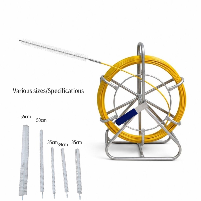
2. Core Components: Rod Body, Reel Frame, Pulling Head and Transport Wheels
Although different manufacturers use different structures, a professional fiberglass duct rodder normally consists of four main components.
2.1 Fiberglass Rod Body
The rod is the primary working component.
Its diameter and construction determine how easily it can travel through a duct and how much pushing force it can tolerate.
Typical commercial duct rodders are available in several diameters, often ranging from approximately 4 mm to 16 mm, although the exact available sizes vary by manufacturer.
A smaller-diameter rod is generally easier to maneuver in narrow ducts, while a larger-diameter rod typically provides greater stiffness and pushing capability.
The correct choice should therefore consider:
Conduit internal diameter
Total installation distance
Number of bends
Cable type
Required pushing force
Available access points
2.2 Reel or Steel Frame
The reel keeps the fiberglass rod organized during transportation and deployment.
A well-designed frame should:
Protect the rod from excessive bending
Allow smooth rod feeding
Provide a stable base during operation
Prevent uncontrolled reel movement
Make storage easier after installation
Many professional models use a steel frame or cage combined with a hand-operated brake. Manufacturer operating instructions recommend positioning the rodder securely and horizontally before operation and controlling the cage while feeding or retracting the rod.
2.3 Pulling Head
The pulling head is located at the end of the fiberglass rod.
Its primary function is to provide a connection point for:
Pulling rope
Electrical wire
Fiber optic cable pulling accessories
Cable grips
Swivel connectors
Other pulling attachments
The connection should be secure and aligned with the pulling direction.
The pulling head is also one of the components most exposed to impact during operation. Manufacturer instructions specifically warn users to protect the drawing head from damage and to ensure the end fitting is properly stored inside the frame after use.
2.4 Transport Wheels
For long working lengths, a duct rodder can become difficult to move manually.
Integrated wheels make it easier for crews to transport the unit between manholes, construction areas, trenches, and conduit entry points.
When selecting a wheeled model, look at:
Wheel diameter
Frame stability
Ground clearance
Handle design
Overall equipment weight
Ease of movement over rough terrain
For civil engineering and underground construction projects, mobility can be almost as important as rod specifications.
3. Key Specs Breakdown: 4 mm–16 mm Diameter, Breaking Tension and Working Length
Choosing a duct rodder based only on its advertised working length is a common mistake.
Three specifications deserve particular attention: rod diameter, working length, and mechanical load capacity.
3.1 Rod Diameter
The diameter affects stiffness, flexibility, weight, and pushing performance.
A simplified selection approach is:
Rod Diameter Typical Advantage Suitable Applications
4–6 mm Highly flexible, easy to handle Small conduits, short cable runs
6–9 mm Balance of flexibility and stiffness Telecom and FTTH work
9–12 mm Greater pushing capability Medium/long ducts
12–16 mm High stiffness and durability Large ducts, civil engineering, demanding runs
These ranges are practical selection categories rather than universal standards. Actual performance depends on rod construction, resin system, reinforcement, temperature, duct geometry, and manufacturer specifications.
3.2 Working Length
Working length determines how far the rod can travel before another access point or rod extension is required.
Common considerations include:
30 m
50 m
80 m
100 m
120 m
150 m
200 m or more
A longer rod is not automatically better.
If most of your work involves short FTTH or building-conduit installations, carrying an oversized 200 m rodder may add unnecessary weight and reduce maneuverability.
For underground infrastructure, however, longer working lengths can reduce the number of access points required during a cable installation.
3.3 Breaking Tension and Working Load
Breaking tension is the maximum load at which a component or rod is expected to fail under specified test conditions. It should not be treated as the recommended working pulling force.
For real installations, always follow the manufacturer's rated working load and the cable manufacturer's maximum allowable pulling tension.
This distinction is particularly important for fiber optic cable because excessive pulling force can damage the cable even when the duct rod itself remains intact.
A 2026 technical guide, for example, recommends monitoring pulling tension during long duct runs and matching the pulling method to the cable type.
3.4 Marked Length Scale
A marked fiberglass rod provides another useful feature: the operator can see how much rod has entered the conduit.
This helps the crew estimate:
Distance already covered
Remaining rod length
Approximate duct length
Location of resistance
Progress during long cable pulls
The scale can reduce repeated manual measurement and communication between workers.
However, claims such as “a marked scale saves exactly 30% of installation time” should only be used when supported by controlled field-test data. In practice, the time savings depend on duct complexity, crew size, access points, and installation method.
4. Step-by-Step Usage: Feeding Through Conduit, Connecting Cables and Avoiding Jams
Correct operating technique is just as important as selecting the correct duct rodder.
Step 1: Inspect the Work Area
Before inserting the rod, check:
Conduit entrance and exit
Duct diameter
Approximate duct length
Number of bends
Existing cables
Water, mud, debris, or obstructions
Condition of the rodder
The fiberglass rod should be inspected for cracks, serious surface damage, exposed fibers, or damaged end fittings.
Step 2: Position the Rodder
Place the rodder near the conduit entrance on stable ground.
The reel should be positioned so that the rod can feed naturally into the duct without creating sharp bends at the entrance.
A manufacturer's operating procedure recommends placing the rodder securely and horizontally and ensuring that the frame components are properly positioned before feeding the rod.
Step 3: Feed the Fiberglass Rod
Insert the pulling head into the conduit and begin pushing the rod forward.
Use smooth and consistent pressure.
Do not aggressively force the rod when it encounters resistance.
A duct-rodder operating guide specifically warns against using mechanical means to force the rod through difficult bends.
Step 4: Handle Bends Carefully
When the rod reaches a bend, reduce pushing force and allow the rod to follow the conduit geometry.
If resistance suddenly increases:
Stop → Reverse slightly → Check the situation → Continue slowly
Do not keep pushing harder simply because the rod has stopped moving.
Possible causes include:
Excessive bend radius
Blocked conduit
Mud or debris
Incorrect rod diameter
Damaged rod tip
Existing cable interference
Step 5: Reach the Exit Point
Continue feeding until the pulling head reaches the opposite access point.
For long duct systems, communication between the operators at both ends can significantly improve coordination.
OSHA requires reliable communication among employees involved in certain underground electrical work and specifically addresses communication and safe positioning during duct-rod operations.
Step 6: Attach the Cable or Pulling Rope
Once the rod reaches the destination, securely connect the pulling head to the cable or pulling rope.
The connection should:
Be mechanically secure
Avoid sharp protrusions
Maintain alignment with the pulling direction
Match the cable's allowable pulling force
For delicate cables, a suitable pulling grip or swivel can help reduce twisting and unwanted stress.
Step 7: Pull the Rod Back
Pull the rod back through the duct while bringing the cable or pulling rope with it.
Avoid uncontrolled or excessively rapid pulling.
The rodder should be retracted through the guide rather than relying on uncontrolled reel rotation. Manufacturer instructions specifically recommend pulling the rod back through the cage eye and storing it properly inside the frame.
5. Common Mistakes to Avoid in Narrow Ducts, Bends and Underground Manhole Operations
Many duct-rod failures are caused not by the fiberglass material itself, but by incorrect operating practices.
Mistake 1: Choosing a Rod That Is Too Large
A large-diameter rod may provide greater pushing stiffness, but it can become difficult or impossible to pass through small conduits and tight bends.
Always compare rod diameter with the actual internal diameter and geometry of the duct.
Mistake 2: Forcing the Rod Through a Jam
When resistance suddenly increases, excessive pushing force can damage the rod or pulling head.
The safer approach is to stop and determine why the rod is blocked.
Mistake 3: Ignoring Existing Cables
Existing cables may occupy part of the duct and change the available pathway.
They may also be vulnerable to damage from excessive pulling or movement.
OSHA requires workers to identify cables being worked on and protect other cables from damage in applicable underground electrical installations.
Mistake 4: Allowing Excessive Rod Bending
Fiberglass is flexible, but it is not indestructible.
Repeated sharp bending can damage the rod structure and shorten its service life.
Mistake 5: Neglecting Manhole Safety
A duct rodder may be a simple cable-pulling tool, but underground manhole work introduces additional hazards.
For telecommunications work, OSHA requires appropriate guarding around manhole openings and requires atmospheric testing before entry into manholes and unvented vaults.
For applicable underground electrical installations, OSHA also specifies requirements concerning access, equipment lowering, attendants, communication, and duct-rod operations.
Therefore, the rodder operator should never treat a manhole as simply another cable access point.
6. Maintenance Tips to Extend Service Life for Daily Cable Laying Work
A fiberglass duct rodder can provide years of service when it is stored and handled correctly.
6.1 Clean the Rod After Use
Remove:
Mud
Sand
Soil
Lubricant residue
Chemical contamination
Water
Dirt left on the rod can increase friction during the next installation.
6.2 Inspect for Damage
Before and after major jobs, inspect:
Fiberglass surface
Pulling head
Connector
Rod guide
Reel frame
Brake
Wheels
Fasteners
Look especially for cracks, splinters, severe abrasion, or loose fittings.
6.3 Protect the Pulling Head
The pulling head should not be allowed to strike concrete, steel structures, or other hard surfaces unnecessarily.
It should be stored securely inside the frame when the rodder is not being used.
6.4 Store the Rod Correctly
Keep the rodder:
Dry
Clean
Protected from unnecessary impact
Away from excessive heat
Properly wound inside the frame
Manufacturer instructions also recommend storing the duct rodder in a suitable shaded location.
6.5 Check the Reel and Brake
The reel should rotate smoothly without excessive wobble.
The brake should provide sufficient control during deployment.
A damaged brake can allow uncontrolled movement of the rod and increase the risk of tangling or injury.
7. Quick Selection Checklist for Telecom, FTTH and Civil Engineering Projects
Before purchasing a fiberglass duct rodder, use the following checklist.
For Telecom Projects
Look for:
Medium rod diameter
Good flexibility
Reliable pulling head
Clear length markings
Easy transport
Corrosion-resistant components
Telecom contractors often benefit from a balanced rodder that can handle different conduit sizes without becoming excessively heavy.
For FTTH Installation
Prioritize:
Smaller and more flexible rod options
Lightweight frame
Easy manual operation
Accurate length markings
Smooth pulling-head connection
Compact transport dimensions
FTTH installations may involve building entrances, small underground ducts, residential pathways, and relatively tight conduit systems.
For Civil Engineering
Prioritize:
Larger rod diameters where appropriate
Long working lengths
Heavy-duty steel frame
Large transport wheels
High-quality rod construction
Robust pulling accessories
Easy maintenance
Civil engineering projects may involve longer ducts, deeper infrastructure, larger conduits, and more demanding site conditions.
Quick Buying Checklist
Before placing an order, confirm:
□ Rod diameter
Does it match the conduit size and bend conditions?
□ Working length
Is it long enough for the longest planned cable run?
□ Working load
Does the rated capacity match the pulling method?
□ Pulling head
Is it compatible with your cable or pulling accessories?
□ Length markings
Can operators quickly estimate installation progress?
□ Reel/frame
Is it stable and durable enough for your jobsite?
□ Wheels
Can the equipment be transported easily?
□ Replacement parts
Are pulling heads, connectors, guides, and other components available?
□ Storage
Can the unit be protected and stored properly between projects?
8. Final Thoughts: Why a Marked Length Scale Model Saves Time On Site
A fiberglass duct rodder is more than a simple flexible rod. It is a complete cable-installation system that combines a fiberglass pushing member, reel frame, pulling head, guide system, and often transport wheels.
For professional cable installation teams, the best model is not necessarily the one with the largest diameter or longest working length.
Instead, the right duct rodder should match the actual project:
Conduit size + duct length + bends + cable type + pulling force + working environment
A marked length scale is particularly valuable for long-distance cable installation because operators can monitor how much rod has entered the duct without repeatedly measuring the route. This can improve communication, progress tracking, and troubleshooting when resistance occurs.
However, the exact time saving depends on the project and should be validated through actual field testing rather than assumed to be a fixed percentage.
Ultimately, a properly selected fiberglass duct rodder can help cable installation teams establish pulling paths more efficiently, reduce unnecessary manual work, and improve consistency across telecom, FTTH, underground utility, and civil engineering projects.
The key is to treat the duct rodder as part of the entire installation process—not simply as a tool for pushing a rod through a pipe.